General
Life
Accessibility Options

General

General Products
Simple & Transparent! Policies that match all your insurance needs.


Scan to download

Life

Life Products
Digit Life is here! To help you save & secure your loved ones' future in the most simplified way.

Scan to download

Claims
Claims
We'll be there! Whenever and however you'll need us.

Scan to download
 General
 Life
Life
Renewals
Resources
Resources
All the more reasons to feel the Digit simplicity in your life!

Scan to download
Our WhatsApp number cannot be used for calls. This is a chat only number.


10000+ Cashless Garages
1.5 Cr+ Policies Sold


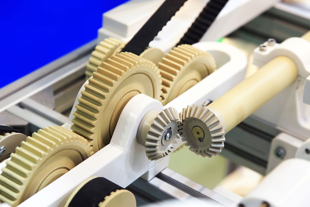
Gears and their mechanical features are widely used throughout industries to transmit power and motion to several mechanical devices. It plays an important part in the automobile industry, clocks, instruments, factory equipment and several other sectors.
This mechanism is an efficient means to alter the rotational speed, change the direction of motion or alter the axis on which the rotary motion is occurring.

Gear is a roller-shaped component of a machine with teeth in its outline structure that transfers speed and torque from one shaft to another. Gears help to obtain different torque and speed ratios or change the direction of the driven or driving shaft.
Gears or cogs consist of cut teeth in the cogwheel or gear wheel. These teeth mesh together and transfer speed and torque.
Gears are available in several constructions, configurations and designs for various industries and applications. Below are gear design characteristics explained in detail:
Most gear teeth sit around a cylindrical gear body with a circular face. However, some gears are also non-circular.
Circular Gear: Circular gears can feature triangular, elliptical, and square-shaped faces. Systems and devices that employ circular gears feature constancy in gear ratio.
Non-Circular Gear: Non-circular gears feature variable torque ratio and speed. It enables these gears to fulfil irregular or special motion requirements.
Cogs or gear teeth feature several characteristics relating to their tooth construction and design. The several construction and design options available for gear teeth are as follows:
Gear Teeth Structure: A gear tooth structure depends on the type and application of the gear. Manufacturers either insert the teeth directly into these cuts or place them separately in the cut. However, sometimes the gear teeth wear off due to usage. If the teeth are embedded inside the cut, the whole gear must be removed.
Gear Teeth Placement: Here, the teeth of a gear sit on the inner or outer gear body surface. This is what happens in external, internal and assembled pairs:
The tooth profile refers to the cross-sectional shape of the gear’s teeth. It influences a gear’s performance features, including the experienced friction and speed ratio. There are three main types of tooth profiles. It includes – trochoid, involute, and cycloid.
While people use trochoidal gears in pumps, they use cycloid gears in clocks and pressure blowers.
Involute tooth gear consists of a curve that forms a locus shape. This shape is necessary as it generates constant pressure in the gear performance.
The most commonly used profile is involute. You can use it in several applications.
The gear axes configuration defines the axis orientation. It is along which the gears rotate and the gear shafts lay. There are three principal axes configurations, including:
Parallel Gear Configurations:Parallel configurations have gears attached to the spinning shafts located on the same surface and parallel axes.
Some gears that use parallel configurations include internal gears, helical gears, spur gears, and some pinion and rack gears.
Intersecting Gear Configurations: Bevel gears, including spiral, miter, and straight bevel, are among the gear groups that use intersecting configurations.
In this configuration, gear shafts intersect with each other within the same surface. Just like parallel configuration, this configuration has high transmission efficiencies.
Non-Parallel And Non-Intersecting Configurations: Non-parallel and non-intersecting assembling have rotating units on the cross-axis that are not parallel and do not cross on the same surface. This assembly has low motion and transmission power efficiency compared to other configurations.
Some of its examples are hypoid, screw and worm gears.
Besides these design characteristics, there are several other considerations that manufacturers and industry professionals keep in mind before they design and select a gear for an application. Some of the other factors that play a significant role during construction are:
Surface Treatments
Number of Teeth
Lubricant Type and Method
Tooth Angle
Construction Material
Depending on the design characteristics mentioned above, several gear types are available in the market. The following are the most common gear types that manufacturers use:
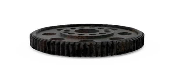
Spur gears have straight teeth that manufacturers cut or insert parallelly inside the gear shaft on a cylindrical gear body. In these gears, the teeth are parallel to the axis of the shafts. Therefore, meshing with another spur gear transmits power in a parallel shaft.
Uses
Manufacturers use spur gears for a variety of mechanical applications, such as:
Power plant machinery
Clothes washing and drying machines watering systems
Pumps
Clocks
Material handling equipment
Gear train
Like spur gears, helical gears use parallel axis configuration along with mated gear pairs. However, if there is proper alignment, they can drive non-parallel, non-intersecting shafts. These gears are cut at a 45-degree angle to the axis and have helicoid teeth on a cylindrical roller. Helical gears are available in single-helical and double-helical designs. Some of the variants of helical gear include herringbone and screw gears.
Uses
The following are the uses of helical gears:
Pumps
Generators
Automobile transmissions
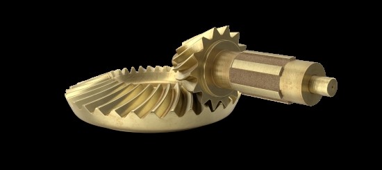
These are conical in shape, and the teeth of bevel gears sit around its conical surface. Manufacturers use these gears to transmit power and motion between intersecting shafts in some applications that need a change around their axis of rotation. Manufacturers make bevel gears with alloy steels, cast steel and plain carbon steel. The configuration angle for bevel gears is 90 degrees. Some of the more common types of bevel gears include zerol, straight, and spiral gears.
Uses
Automotive
Heavy equipment
Aviation
Industrial plant equipment
Hand tools like drills and planers
Marine transmission
Worm gear consisting of worm wheels transmits power to a shaft that does not intersect and is at an angle. By changing their rotation, these gears transmit motion and power between non-parallel, non-intersecting shafts. The worm gear design comprises the driving or screw gear and the driven gear, which is a spiral-toothed helical gear.
Uses
Below are the uses of worm gears in several industrial needs:
Forest, energy, and unit-handling industries
Small conveyors
Package handling equipment
Lifts and elevators
Farm machinery
Food industry
Beverage industry
Automotive
Rack and pinion gears are gear pairs that consist of a gear rack and a cylindrical gear or pinion. The gear rack is a flat surface with an infinite radius and straight teeth that are inserted on the bar surface. However, the gear rack's teeth are either parallel or angled depending on the pinion gear type with which manufacturers assemble it.
Uses
Some of the applications of rack and pinion gear pairs include the following:
Steering system of automobiles
Transfer systems
Weighing scales
Below are the characteristics of gears by type:
| Gear Types | Characteristics |
| Spur Gear | • Easier manufacturability • A high degree of precision and efficiency • Lack of axial load • Circular gear body • Efficient to handle high-speed and high-load • No thrust force |
| Helical Gear | • Produce less noise and vibration • Less prone to wear and tear • Can easily engage with other gears due to angled helical teeth • Handle greater load • Circular gear body • Less impact loading |
| Bevel Gear | • Can work at other angles apart from 90 degree • Able to handle thrust and radial loads • Assemble at the optimum position for excellent performance • High efficiency • Simple Design • Easy to manufacture |
| Worm Wheels | • High gear ratios • Capable of substantial speed reduction • Maintain quiet and smooth operation • Self-locking mechanism |
| Rack and Pinion | • Low manufacturing cost • Simple Design • High load-carrying capacities • The use of aluminium and steel gives maximum strength to these gears |
Shifting of gears or gear changing is the mechanism to change from one gear arrangement to another smoothly. You can change/shift gears up or down in an automobile. The basic explanation is you change from one gear to another as the car speed increases and down when you require power from the engine.
The gears determine the amount of power available from the engine. There are various forms available for changing or shifting gears, such as:
Derailleur gears
Hub gears
Manual transmission
Automatic transmission
A gear functions on the fundamental thermodynamics principle. The law of conservation, or the first law of thermodynamics, defines that energy can neither be created nor be destroyed. It is conservative. Energy can be transformed from one form to another.
Power is the function of the shaft's torque or force in rotary motion and speed, P = TV. Thus, when we connect a larger gear on the driven shaft and a small one on the driving shaft, the driven shaft speed reduces per unit rotation of the driving shaft.
Since power is conservative, according to this theory, the torque of the driven shaft enhances as per the ratio of driving gear to driven gear. So, by applying multiple gear designs, we can get several torque and speed combinations of the driven component.
Manufacturers use gears in several mechanical devices. So, you will find several types and designs of the same. Some significant factors that you must consider when designing and electing a gear include:
The operational conditions of gear generally influence optimal design and gear type. It is because these conditions can affect the gear’s durability and performance levels. Additionally, some other conditions which might affect a gear are the noise and vibration that it generates, the amount of weight that stresses on it, friction and stress that its teeth absorb.
Some of the environmental conditions that affect the functioning of gear include:
Temperature
Humidity
Sanitation
Cleanliness
These conditions affect several gear design factors, which include surface treatments, the construction material, and the lubricant method and type.
Change in directions also influences the optimal gear type since each type features a specific configuration. For example, screw gears use a non-parallel, non-intersecting configuration, bevel gears use intersecting arrangement, and spur gears use a parallel layout.
Dimensional specifications also affect the functioning of a gear. Deviating from a standard tooth profile means adjusting a gear tooth’s thickness. This adjustment alters the centre distance and the strength of the gear’s teeth.
When designing a gear, the manufacturing cost depends on multiple factors. It includes surface treatment and finish, construction materials, gear design, precision standards, and lubricant or lubrication methods.
Gears transfer motion and torque between machine components in mechanical devices. As per the design and construction of a gear pair, they can alter movement and direction and increase their torque or output motion.
These specifications and requirements determine the optimal gear type, configuration and design.
There are no specific gear design standards mentioned in any manual. Therefore, gears are designed depending on the standards set by a manufacturer or as per the design and specifications of a particular machine or system.
Gears apply to almost everything that we use in our daily life. However, manufacturers use it to build certain applications depending on its specific structure and design. Several gears are available in an array of commercial, residential, and industrial usages. The following is the application of gears:
Washing machines have gears
Gears are applicable in the toy industry
Household appliances and dryers use gear
Gears are applicable in railways and trains
Gears are also available in marine systems
Material handling, lifts, and elevators need gears
Gears are used in water systems, clocks, and pumps
Gears are also used in aerospace and aircraft industries widely
Manufacturers use them in weighing scales and other measuring instruments
The automobile industry, like, cars, bikes, and other transportation, uses gears during manufacturing
It is necessary to know about gear terminology when designing a gear. Here they are:
Apart from the above, there are several other gear terminologies that you must remember when working with this component.
So, now you have a basic understanding of what is a gear, its various types, applications and considerations. Before designing one, ensure to keep all these factors in mind. It is ideal if you watch a video of the functioning of a gear or seek guidance from a mechanic to understand its functioning practically.
Explore Insurance Coverage for Your Vehicle

